Long Wireless Transmission
Some months ago, I got a suggestion from my Forum user, which had a specific problem: the soil moisture sensors should be at about 500m distance from the Hydrosys4 central unit.
The suggestion was to use low frequency transmitters to reach the sensors. The HC-12 is a low budget (less than 7USD) transceiver which works at 433 MHz. This frequency is particularly suitable for the long distance transmission and it is free to use in many countries, although the regulation about Max transmitting power may vary from country to country.
According to the datasheet the HC-12 can reach up to 1.2Km range, so it should be suitable for small farms. Of course as in all wireless transmission this distance is highly variable due to several conditions but normally in open field we should be close to quite good conditions to get a decent range.
In this blog I’m going to detail my implementation to transmit the data from my Digital Soil moisture sensors to the Raspberry using the HC-12
HC-12 module
The HC-12 module its a very interesting object for the price they sell it. 433MHz, more than 100 channels, possibility to set the TX power and TX mode, and ability to transmit and receive.
Testing:
The HC-12 can be easily connected to the Raspberry, and to the Arduino module.
During the testing phase I tested both the interface with Raspberry and the interface with Arduino. With the Raspberry I had no issue since the beginning. With the Arduino the HC12 module I’m still in testing phase to verify the interface is stable.
I have to admit that I purchased clones, so I should accept some quality issue.
I discovered that the module that I purchased come with the SW release 2.4 which is not the latest and moreover seems not to be compatible with the release 2.6.
Then looking on Internet, it is possible to see that most of the clones under perform in terms of transmitting power. Fortunately it seems that somebody found a fix for it.
Here a Link to the video describing the fix: https://youtu.be/ZfBuEAH-Q8Y
Here the User manual of the HC12 v2.4 for reference: http://statics3.seeedstudio.com/assets/file/bazaar/product/HC-12_english_datasheets.pdf
Testing Phases:
- Raspberry interface wit HC-12 (Done)
- Arduino interface with HC-12 (Ongoing stability check)
- HC-12 Wireless Setting: Channel, Power, Tx Mode (Done)
- Long range distance (To be done)
- Multiple HC-12 with Sensors Connection (Done with two HC-12 with sensors)
System Overview
The system is made as follow:
The HC-12 connected to the raspberry act as the main receiver, it will receive the signal from the several HC-12 connected to the sensors. As the HC-12 can only receive from one channel at the time the HC-12 in the sensor node need to transmit at different time.
The HC-12 in the sensor node requires an Arduino (nano) which will act as interface between several sensors and one HC-12. The HC-12 in this location will mainly transmit the sensor data and receive the acknowledge from the main HC-12.
It should be possible to connect several HC-12 with several sensors to the main HC-12, I programmed a simple Aloha protocol which in case of collision due to HC-12 transmitting at the same time, give the possibility to retry the transmission.
The data transmitted is ciphered, and contain a timestamp to uniquely identify the packet.
Main HC-12 Raspberry side
NOTE: power supply is extremely important, during one of my testing I used a Huawei fast Charger, the Raspberry was working without problems but the HC-12 did not work. Only after hours of testing I realized it was the battery charger. As seen, the HC-12 is quite sensitive to poor battery chargers.
This is the HC-12 is in charge of receiving the radio signal from the sensors and send the acknowledge.
Wiring the HC-12 to the Raspberry:
For the physical connection of the HC-12 with the Raspberry, only 3 wires and power are needed as described below:
- HC-12 TX -> RPi GPIO 15
- HX-12 RX -> RPi GPIO 14
- HC-12 Set -> RPi GPIO 04
- HC-12 VCC -> +5v
- HC-12 GND -> GND
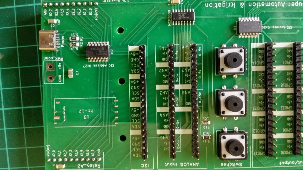
In case you are interested in purchasing the SuperHat from my shop, the board already have the required space to conveniently solder the Module:

Once the HC-12 is properly connected to the Raspberry, the Hydrosys4 requires to be reboot.
Starting from Hydrosys4 release 3.32 the HC12 will be fully integrated in the Setting Menu.
After wiring all the required connection and enabling the Serial (See chapter below). It is also necessary to check if any of the following pins: 4,14,15 are used in the Hardwaresetting table. If this is the case, the setting including these PINs have to be deleted, otherwise the following menus will not appear. After deleting the config with the PIN 4, 14, 15 reboot the Raspberry.
In the “setting” page there is a button named “HC-12 wireless setting”. Clicking on the button will show this interface:
NOTE: this interface will appear only if the HC-12 is properly connected to the raspberry.

All the parameters in this page should be the same for All the HC-12 on the sensor nodes.
After the wiring and the wireless setting is done, then it is time to insert the Sensor in the Hydrosys4 hardware table so that the Sensor can be visible in the various menus.
To do so, it is required to give an address for the sensor (less than 10 characters) which will act as identifier for the sensor on the wireless side. This will be in the Title field.
Let’s assume the identifier is “primo”. We need to go to the “hardwaresetting” nemu, click on edit table, and add the following line:

note that the Title filed is “primo”. The time normally should be set to 30 minutes or more (00:30:00)
Enable UART interface on Raspberry:
In case you have installed the Hydrosys4 using the installation procedure rather then the .img file. Then the UART should be enabled as follow:
- Start raspi-config:
sudo raspi-config. - Select option 3 – Interface Options.
- Select option P6 – Serial Port.
- At the prompt
Would you like a login shell to be accessible over serial?answer ‘No’ - At the prompt
Would you like the serial port hardware to be enabled?answer ‘Yes’ - Exit raspi-config and reboot the Pi for changes to take effect.
HC-12 Sensor Node
On the sensor side, we require one HC-12 and an Arduino that acts as interface plus several soil moisture sensors.
For the Arduino you can download the sketch here: https://github.com/Hydrosys4/Arduino-HC12-DigiHygro
There are two types of sketch files,
- the HC-12encoding_vX.X. used for the connection with my digital soil moisture sensors.
- the HC-12encoding_analog_vX.X. use to read the arduino analog inputs, for generic analog sensors.
Before loading the sketch on the Arduino, it is necessary to open it with a standard text editor and adjust some of settings (unless you want to use the default).
In the sketch (main.cpp) there are some points which highlights where the changes can be done.
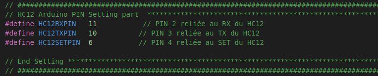
The above part indicates the PIN of the Arduino to be connected to the HC-12. I suggest to leave them unchanged.
- HC-12 RX -> Ardunio 11
- HC-12 TX -> Ardunio 10
- HC-12 Set -> Ardunio 6
NOTE: The Code uses a random seed generator in Arduino which requires the PIN A0 to be left afloat.
Then the second section includes several settings:

MAX_Sensors: indicates the max number of Digital Hygrometers sensors that can be connected to the Arduino. (tested max 2)
SLEEP_time: is the time the node will be sleeping among two transmissions to the main node. As the soil moisture is not a fast changing parameter, then it is recommended to set it to more than 30min (>1800000 = 30x60x1000) the measure is in mSec.
CipherKey: is the ciphering Key
AT_TX_Mode: suggest to use FU4 which is optimized for long distance communication.
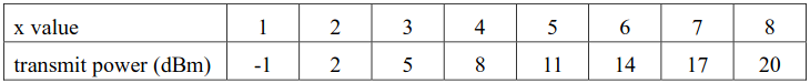
AT_TX_power: The TX transmission power, according to the datasheet the value from 1 to 8 provide the following power.
AT_Channel: is the transmission channel, the values are from 001 to 100.
All the above AT parameters and Cipher Key have to be the same in all nodes and main HC-12.
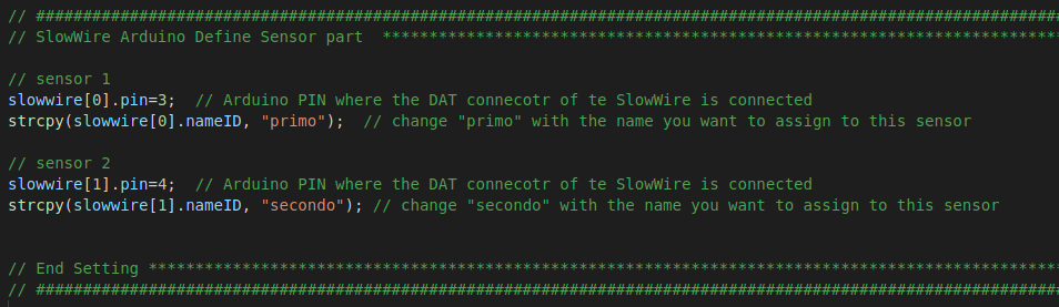
Then t he below parameters are the identifier for the Soil moisture sensor. As in the above paragraph we set one of the sensor identifier as “primo”.
The Sensor have also a PIN number, which is the Arduino PIN where the sensor DAT wire should be connected.
Once the main.cpp is modified with all the parameters, it is time to load it into the Arduino.
For instructions how to upload the SW, there are various SW which can do it. I use platformIO , anyway you can easily find tutorial on internet.
Arduino Nano
I made the testing using the Arduino Nano that uses this ATmega chipset atmeg168.
In theory Arduinos with higher chipset specs should work without problems.
Here a s reference a picture of the Arduino I have used.

This version has a USB port which is very convenient to upload the SW.
As seen in some tutorials, this Arduino type can be powered also with 3.3v which is very useful for solar setup.
Unfortunately the power consumption in deep sleep mode is around 10mA, which is very High compared to other Arduino boards like the PRO Mini.
The arduino sketch uses a power saving library http://sparks.gogo.co.nz/SimpleSleep.zip, (seems to be a very good library) some additional steps to include the libraries are required before uploading the sketch.
Arduino PO mini (3.3v)
I also tested the implementation with the Arduino PRO mini, the version at 3.3v.

This device does not have a USB port, so to be programmed it requires a USB adapter.
I used a standard USB to Serial adapter, even if this generic device in theory should not be used with the PRO Mini, I discovered (thanks to youtube) that if you click the reset button at the right time, the SW can be definitely loaded in to the Arduino.
I tested the SW and it worked normally.
Just as quick check I measured that the system when in sleep mode consumes around 0.1mA , while when working it reached picks of 29mA.
The system is designed to sleep between consecutive transmissions to save energy. If the transmission is set every 30min, the energy consumption should be very limited and suitable for a Solar systems.
